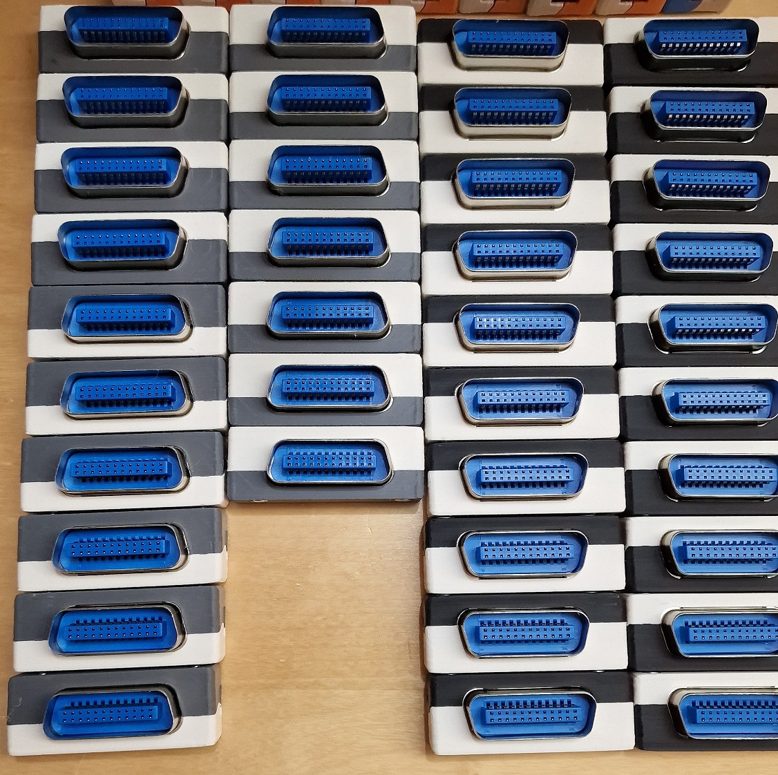
The new HW revision picks up some things that I and other misliked:
- The REV 1 HW - when put beeing assembled into its housing did have change to colide with parts of the instruments body. Especially for Keysight equipment. This new HW revision follows the formfactor of an original GPIB cable to get rid of this mechanical constraint.
- The REV 1 HW required to enter the bootloader with a tweezer. REV 2 has a button. Hold it a few seconds and the bootloader is entered.
The software will always stay the same, no matter if REV1 or REV 2.
I have built many of those adapters myself so far and have developed trust in the design:

All files related to HW are located in this folder. Gerber file, BOM, Kicad design files.
Mount only the SMD components. This means: DON'T mount the GPIB connector yet.
On edge you can find a mounting point for a pinheader - 45 degrees angled. Mount 2-3 pin pinheaders here and you now have a 6 pin ISP programming port with standard pinout for your favorit AVR programmer. Program the bootloader. Pin 1 is marked on the PCB to allow you connecting the ISP cable in the correct orientation.
For initial programming an AVR ISP adapter is needed to program the "Bootloader.hex" file.
It is very important, that the Fuses of the AVR are programmed.
Here an example how to program the bootloader using avrdude (using usbasp programmer): avrdude -c usbasp -p m32u4 -e -Ulock:w:0xFF:m -Uefuse:w:0xcb:m -Uhfuse:w:0xd8:m -Ulfuse:w:0xde:m avrdude -c usbasp -p m32u4 -U flash:w:BootLoader.hex
To program bootloader and application image at the same time using AvrDude, you can use this command: ..\avrdude -c usbasp -p m32u4 -e -Ulock:w:0x3F:m -Uefuse:w:0xcb:m -Uhfuse:w:0xd8:m -Ulfuse:w:0xde:m -U flash:w:TestAndMeasurement.hex -U flash:w:BootLoader.hex
Note, that some programmers use a quite high clock frequency on the programming interface. In case of failures try to decrease the SCK clock frequency!
After programming the file, disconnect and connect the device and a USB drive will show up. Copy the TestAndMeasurement.bin file to this USB drive - ideally using the command line. Example: copy TestAndMeasurement.bin F:\FLASH.BIN.
On Linux, there is a bug with the LUFA mass storage that means it is required to use dd if=TestAndMeasurement.bin of=/mnt/FLASH.BIN bs=512 conv=notrunc oflag=direct,sync.
When done, disconnect USB.
It is now safe to desolder the ISP pinheaders such that the PCB fits into the housing. Any further update can happen over USB using the bootloader.
Preparation:
- Mount the PCB EXCLUDING the GPIB connector.
- Print the housings located in this folder. I print them using 1mm bottom/top/wall thickness, 0.16mm layer height and 30% infil. On my K1 printer it takes 23 minutes to print, on my Ender 5 2.2 hours.
- get 2 20mm M3 screws and 2 M3 nuts
- get a USB connector "24P Male solder type" from e.g. Aliexpress
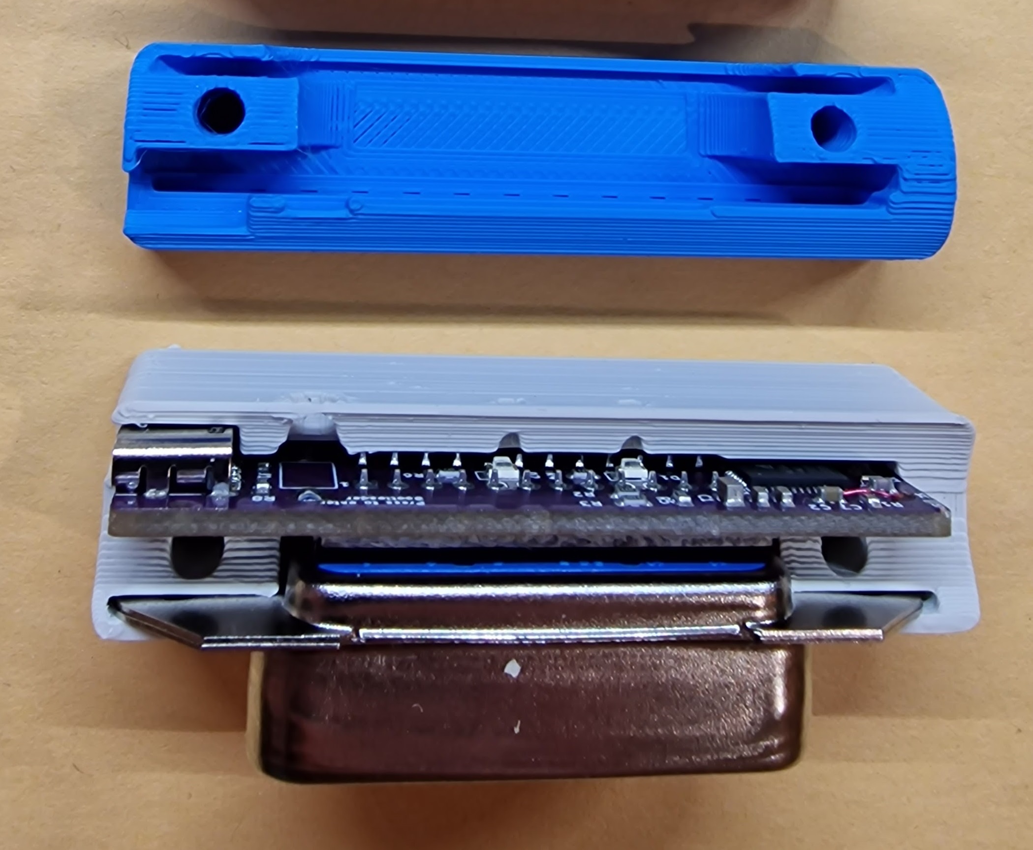
If you have everything in place and prepared, insert the PCB including the GPIB connector (unsoldered!) into the bigger part of the housing:
Then solder 2 pins of the GPIB connector and take the PCB out of the housing again to solder all pins. (This step is required to ensure that the GPIB connector has the right distance to the PCB and fit into the housing)
As a next step insert the PCB into the big part of the housing again. It has a relatively tight fit - to ensure mechanic stability.
Then put the smaller part of the housing on top of it, insert the screws (they can be pushed hard to destroy the "membrane" first time) and nuts and screw it together.
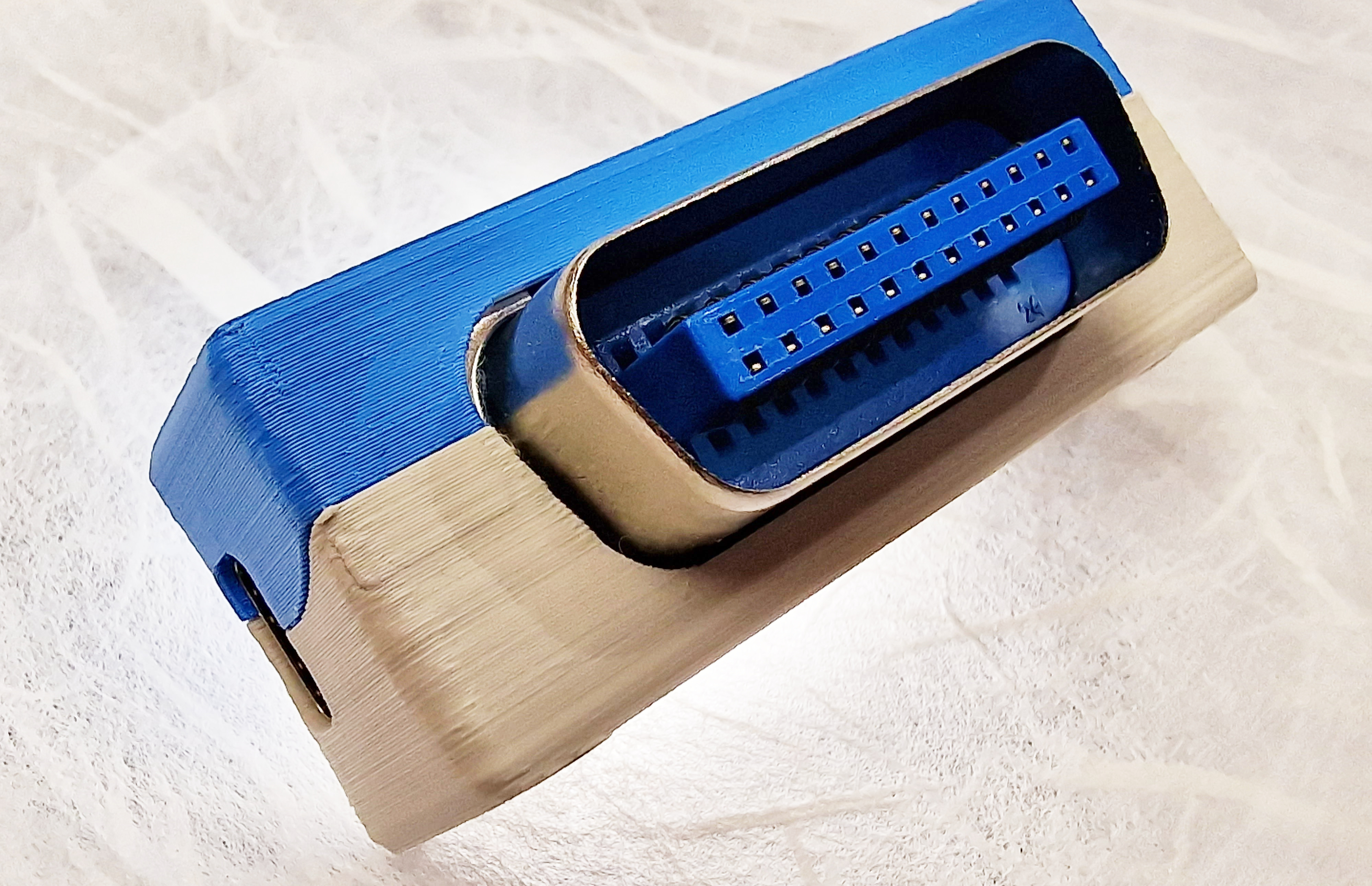
Voilà... your adapter is finished and ready to use :-)
To enter the boot loader at later stages for updates, press the button (bigger hole in the housing) using a pen/paperclip for about 3 seconds. Then a USB mass storage (flash drive) enumerates on the PC where the firmware image can be copied too (see previous chapter).

