This is the original HW design.
It comes in 2 flavors:
- An eagle design which is the root of all designs and my own (xyphro) design.
- A user contributed Kicad design which is also confirmed working correctly.
The software will always stay the same, no matter if REV1 or REV 2.
All files related to HW are located in this folder. Gerber file, BOM, Kicad design files.
Mount all components on the PCB. For REV 1 you can assemble the whole design before putting it together. I mention this explicitely, because for REV 2 it makes sense to mount the GPIB connector only at a later stage of assembly process.
For initial programming an AVR ISP adapter is needed to program the "Bootloader.hex" file.
It is very important, that the Fuses of the AVR are programmed.
Here an example how to program the bootloader using avrdude (using usbasp programmer): avrdude -c usbasp -p m32u4 -e -Ulock:w:0xFF:m -Uefuse:w:0xcb:m -Uhfuse:w:0xd8:m -Ulfuse:w:0xde:m avrdude -c usbasp -p m32u4 -U flash:w:BootLoader.hex
To program bootloader and application image at the same time using AvrDude, you can use this command: ..\avrdude -c usbasp -p m32u4 -e -Ulock:w:0x3F:m -Uefuse:w:0xcb:m -Uhfuse:w:0xd8:m -Ulfuse:w:0xde:m -U flash:w:TestAndMeasurement.hex -U flash:w:BootLoader.hex
Note, that some programmers use a quite high clock frequency on the programming interface. In case of failures try to decrease the SCK clock frequency!
After programming the file, disconnect and connect the device and a USB drive will show up. Copy the TestAndMeasurement.bin file to this USB drive - ideally using the command line. Example: copy TestAndMeasurement.bin F:\FLASH.BIN.
On Linux, there is a bug with the LUFA mass storage that means it is required to use dd if=TestAndMeasurement.bin of=/mnt/FLASH.BIN bs=512 conv=notrunc oflag=direct,sync.
When done, disconnect and connect USB again and you're ready to use it!
Preparation:
- Mount the PCB EXCLUDING the GPIB connector.
- Print the housings located in this folder. I print them using 1mm bottom/top/wall thickness, 0.16mm layer height and 30% infil. On my older Ender 5 printer a print takes about 2.5 hours.
Assembly is easy: Insert the fully mounted PCB into the power part of the housing.
Then snap on the top part of the housing. Done :-)
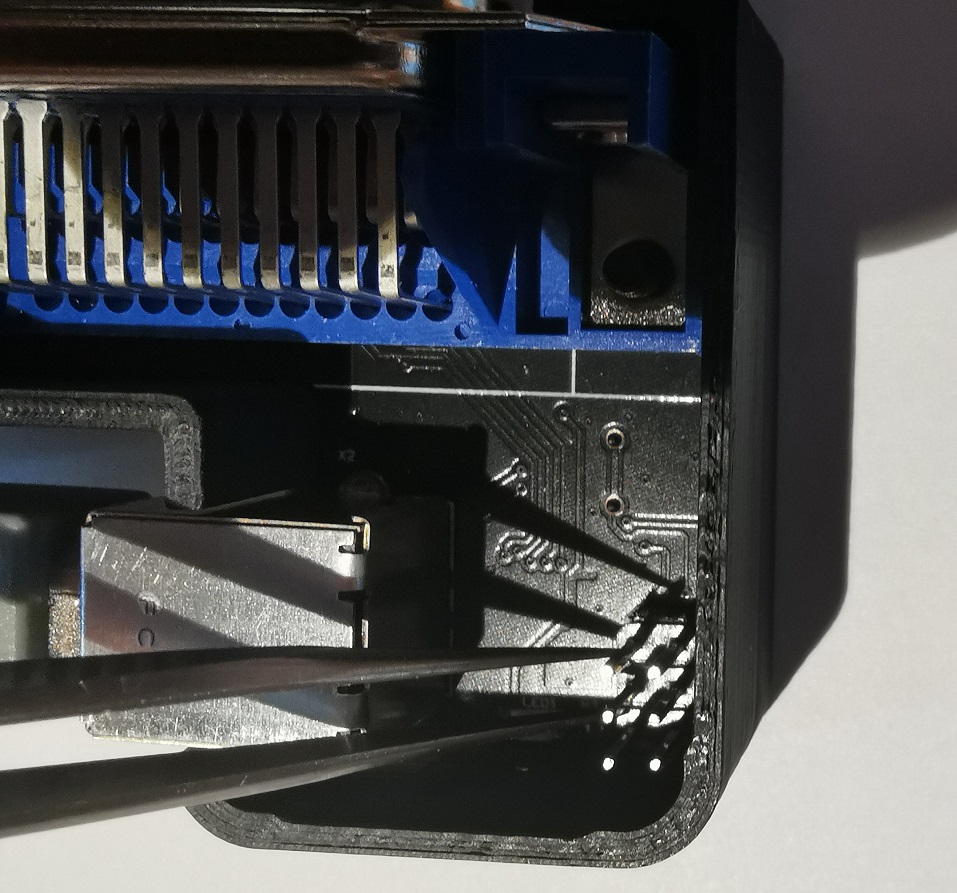
To enter the boot loader at later stages for updates, short circuit the 2 pins of the ISP header, as shown in below picture for about 3 seconds:
Afterwards, a USB drive will show up and you can copy the firmware again to the device, as described in the previous section.
